


Mold design is the backbone of modern manufacturing — from automotive and aerospace to medical devices and consumer goods. This practical guide explains the core components (core & cavity, cooling, ejection, gates & runners), the step-by-step design process, common challenges and future trends such as 3D printing and AI.
What is mould design?
Mould design is the engineering practice of creating tools that shape materials — plastics, metals, glass — into finished parts. A good mould matches the product specification, reduces waste and delivers consistent quality over many cycles.
Key takeaway: mould design translates product geometry into a manufacturable, repeatable tool that meets tolerance, cosmetic and functional requirements.
Why mould design matters in modern manufacturing
- Quality: correct design reduces defects such as warpage and sink marks.
- Cost: optimised tooling lowers scrap and cycle time.
- Scalability: well-designed moulds support high volumes with predictable output.
Key components of a mould
Most moulds share a predictable set of components. Below are the parts you must design and the typical considerations for each.
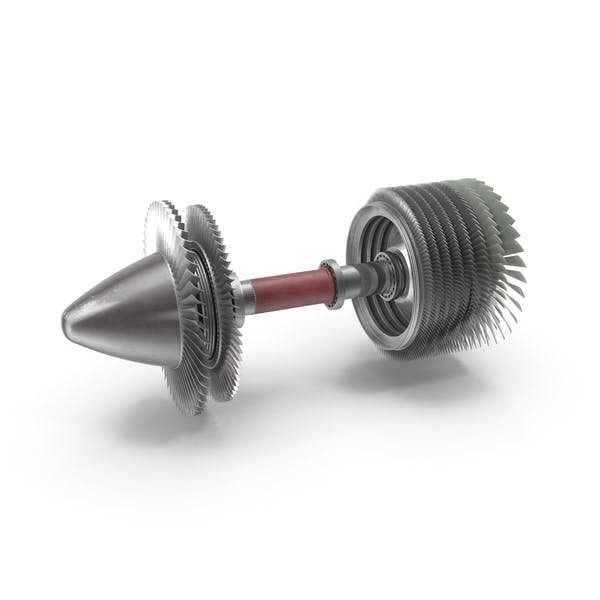
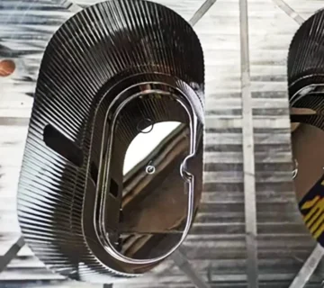
Cavity & core
The cavity shapes the external form; the core creates internal features. Material choice (hardened steel, pre-hardened steel, aluminium or beryllium copper) depends on production volume, thermal needs and wear resistance.
- Design for shrinkage and dimensional tolerance.
- Specifically grade steels for durability in high-pressure, high-temperature cycles.
- Use surface texturing and finishes to meet cosmetic requirements.
Related: Mold Core & Mold Cavity: Differences and Design Considerations
Cooling channels
Effective cooling is vital to part quality and cycle time. Channel layout, diameter, flow rate and coolant choice (usually water; oil in specialised cases) must match the polymer and part geometry.
- Use conformal cooling where straight channels can’t provide uniform temperature.
- Balance channel spacing to avoid hot spots and warpage.
- Simulate thermal performance early in design.
Ejection system
The ejection system safely removes parts without damage. Common elements are ejector pins, sleeves, stripper plates and, increasingly, sensor-assisted ejection for quality control.
- Design ejectors to spread force evenly and avoid marks.
- Consider automatic ejection sensors for high-value or fragile parts.
Related: Ejector Pins in Injection Moulds
Gates & runners
Gates and runners control molten flow into cavities. Correct gate type and runner design reduce defects (air traps, weld lines) and optimise material usage.
- Choose gate type (edge, pin, hot) by part geometry and cosmetic needs.
- Hot runners reduce scrap and improve cycle time for high-volume production.
Related: Injection Moulding Gates & Runners — Types and Design
The role of the mould designer
Mould designers bridge product design and manufacturing. They convert part drawings into CAD moulds, choose materials, design cooling and ejection, run simulations and collaborate with toolmakers.
Core responsibilities
- Design and validate CAD models (SolidWorks, Creo, NX).
- Run mouldflow and thermal simulations to reduce defects.
- Select mould materials and surface treatments.
- Work with production to ensure manufacturability (DFM).
Mould design process — step by step
- Analyze the part: tolerances, wall thickness, undercuts, and cosmetic requirements.
- Select mould type & material: single vs multi-cavity, steel vs aluminium, hot runner vs cold runner.
- Design core & cavity: account for shrinkage and machining allowances.
- Design cooling: channel layout, flow rates, conformal cooling where needed.
- Design ejection & gating: select ejector locations and gate type.
- Simulate: mouldflow, warpage and thermal analysis; revise design accordingly.
- Prototype & test: build tool or 3D-printed prototype; validate dimensions and cycle time.
- Production handover: finalise tool documentation, maintenance plan and inspection points.
Tip: early simulation (before final tooling) saves time and cost — it catches issues such as poor fill, excessive warp and high stresses before expensive machining.
Common challenges in mould design
- Thermal control: uneven cooling → warpage or sink marks.
- Material flow: short shots and weld lines from poor gate placement.
- Cost vs quality: choosing the right material and complexity for the production volume.
- Tool maintenance: wear and corrosion shorten tool life if not designed for serviceability.
Address these with structured testing, simulation, and by involving production engineers early in the design stage.
The future: 3D printing, simulation & AI
Technology is reshaping mould design:
- 3D printing: rapid prototyping and conformal cooling inserts.
- Advanced simulation: more accurate mouldflow and multi-physics analysis.
- AI & ML: optimised designs, predictive maintenance and improved cycle forecasting.
- Sustainability: material-efficient designs and reduced scrap.
FAQs
What is the difference between cavity and core?
The cavity forms the outside shape of a part; the core creates internal features. Together they define final part geometry and tolerances.
How does cooling influence cycle time?
Faster and more uniform cooling shortens cycle time and reduces part-to-part variation. Poor cooling causes warpage and long cycles.
When should I use a hot runner?
Use hot runners for high-volume production where reducing runner scrap and improving cycle time justifies the higher tooling cost.
Which CAD tools are common for mould design?
Popular CAD tools include SolidWorks, Creo (PTC), Siemens NX and Autodesks’ products; mouldflow simulation is often run in Moldflow or Moldex3D.
How long does mould design take?
Typical design time varies with complexity: simple prototype tools can take weeks; complex multi-cavity production tools may take months including simulation and validation.
Need help with mould design or tooling?
We offer professional mould design, CAD modelling, simulation and turnkey tooling services. If you’d like a consultation or a quote, contact our team — we’ll help you evaluate manufacturability, reduce cycle time and lower production costs.
No comment